
XMods or Mini-Z Fet Upgrade
In this section of JFunk Labs we will cover the creation of a DIY external FET board for an xomds or mini-z 1/28 scale radio controlled car using easy to find components.
Before I begin I would like to point out that I am by no means an electronics whiz and the method detailed here may not be the best but it worked for me.
Let's start by explaining what a FET is and why people sometimes need to upgrade them. A FET or Field-Effect Transistor put simply is a bit like a tap. It lets electricity flow from the source to the drain when a small control voltage is applied to the gate.

The FET in a mini-z or xmods car takes power from the batteries to the motor. The FETs on the board can only take so much current before they over heat or fry altogether. This can happen when you are using a high current or "HOT" wound motor. Some people either replace the standard FETs or stack more fets on to to spread the load. Stacked FETs can start to get very hot and if you stack to many the eventually end difficult to fit in the car. The other problem is all that current has to come through the standard board which can create a bit of a bottleneck. This is why I decided to try building my own external FET board.
What you will need -
Soldering iron and solder
De-Soldering wick or gun
Multi meter / Circuit tester ( also very handy for testing other parts of your car )
Helping hands (If you have not come across these they are a small jig for holding electronic components with a built in magnifying glass - very handy)
Thin single core wire
Thin multi core wire
Some thicker good quality wire ( preferably 16 Gauge silicone wire )
Maybe some different colors of wire to stop it getting confusing
FETs of your choice ( I will be using ROHM SP8M4 as they have very low internal resistance)
Some strip board at least 10 wholes wide.
I am also adding a large capacitor to help the explosive power but it is not essential
The hands of a surgeon and balls of steel help as well ;-)
Lets begin! IF you have not soldered before I suggest you read this guide and have a good practice first.
To begin with you will notice that legs on the FETs are very small and and would not match up with the wholes on the strip board so we will need to extend them. You will also noticed as standard the legs are bent downwards wit a kink in the middle. The first thing to do is straighten them out a bit by squeezing them with some plyers ( preferably thin ones ). This will make it easier to solder them.
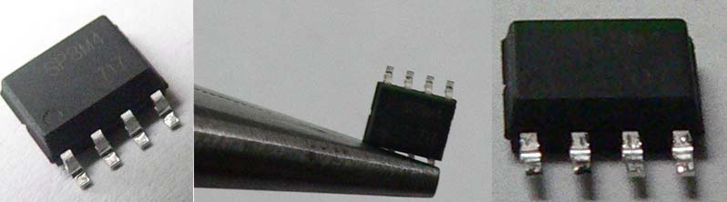
Next look chip - You will see a dot in one corner. The legs on the side with the dot on are the ones we will need to extend, as they are the important ones. The ones on the other side can all be joined together as they are all " drain connectors ". If you want to know what each pin does I have included a diagram -

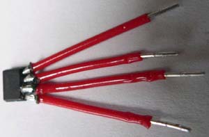
At this point It would be a good idea to prepair some short pieces of your single core wire ready and strip about 1mm off one end and 2-3mm off the other end. I have been using lengths of around 15mm for the extensions so I can then bend them into the right shape to fit under the shell but you can make them shorter ( it looks neater but is more fiddely )

Next Lets get everything set up in the helping hands. We are going to solder the legs one a t a time. Hold the FET in one grip with pins 1 - 4 facing the other grip. Now put a piece of your single core in the other grip and line them up. !! Make sure the two are touching properly !!

Now for scary bit - Your first solder. First get your soldering iron hot, cleaned, tinned and then tap it on the edge of the desk to shake off any excess. Try to press the soldering iron to the pin or wire without touching the other pins. Allow it to heat for a few seconds then carefully apply the solder. If you accidentally solder two pins together don't panic - just clean your soldering iron and re-melt the offending solder. Usually the solder will stick to the iron and come off the pins. If this does nor work use some solder wick or a de soldering gun to remove the solder and start again. Once you have all 4 legs done it will probably look something like this - ( for future reference we will call one of there a spider unit )
If some of your solders are a bit to close for comfort you can cut some small rectangles of electrical tape and slide them in between then rap. Now is a good time to get out your multi meter and check that none of the pins are touching. Mine has a continuity setting but if yours does not just set it to measure resistance. Press one probe to one leg and the other to the other to the next leg and make sure the meter stays on 0. If there is a connection between two pins the board will not work and may fuse your car.
Once you have made as many of these you need for your board it is time to solder them to the strip board. I have started with 6 or 2X3 as This should be plenty for my motor. I believe the standard FETs on my xmod will give up to 3.5Amps.The SP8M4 FETs I am using can each take a sustained drain or between 7 and 9 amps with up to 35 amps serge, so if you multiply that by 3 you ar looking at up to 27amps sustained current and close to 100 serge ( my batteries wont give out that much ). The xeric motor I will be using will draw up to 35 amps when accelerating but will usually run much much below that.
I used a strip board winch was 10 by 10 to give me a bit of future upgrade. all the components will be on the side of the board with no copper strips and the soldering will be on the other side - this will stop short circuiting and make the soldering easier. If we number the copper strips from 0 - 9 going left to right. Solder your first spider unit with pin 1 of the unit going to strip 3 pin 2 to strip 4 ..... Then your second with pin 1 to strip 6, 2 to 7... Here is a crude MS Paint diagram to help explain.

Once you have the legs attached to the board, solder a piece of wire from all the pins on the gate side of the FET on the left to strip 0 and the right one to strip 1. I used a slightly thicker wire for this. Then you can solder more of these in parallel till you are satisfied you have enough. Here is how my 2X3 looked at this stage.
As you can see I am rubbish at soldering ;-)
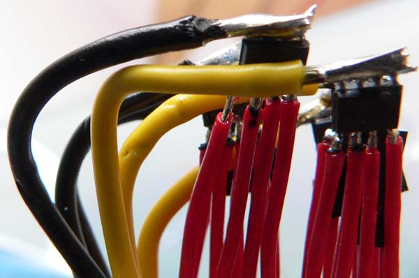
Now take your thin multi core wire and solder it to one of the last wholes on strips 3, 5, 7 and 9 using different colors makes it easier but is not essential. Use a length of 4 inches or so as you can always cut it back afterwards. These wires are the ones we will attach to the board of the car later.
Next take a use a short piece of wire for the power link at the bottom of the circuit diagram which links strips 2 and 6 and then another piece from 4 to 8.
Now turn the board over and solder the power and motor cables using the nice thick 16 gauge wire to strips 0,1,2 and 4 or 0,1,6 and 8 ( this option gives you more space ). To attach them I stripped the wire and soldered it straight to the strip as it would not fit through the hole. If you do this make you get lots of solder on it so it wont come away and wont fray and possibly cause a short. Here is a pick of the underside of the board. You may need to trim some of the strands if the cable you are using is to thick to fit on the strip

If you want to add a capacitor I would advise you put it between strips 6 and 8 paying attention to the polarity. This will supply an extra boost if your batteries are not supplying enough current for the motor. I used a 1000uf cap as I had one lying around. But you can use anything up to .33f .
Once finished it will look a bit like this-

I connected it up to a test board and a cheep motor initially for testing but If you have been careful you can install it straight into the car. Obviously you can bend the spider units down a bit so it fits in the car. It is worth covering the bottom of the board with insulating tape. You can also tape up the spider units if you think they may short but they may get hotter. If you have alternated the fets like in the picture the cables will keep it separate. Make sure your aerial does not touch any part of the unit or it will kill your range permanently.
Now to connect it to your car.
We are going to solder it so it over rides the fets on the bottom of the board. You can either remove the existing FETs by de-soldering or cutting or leave them on the board and bypass them. Clean the FETs on the car so you can see where the dot is then you need to match up the pins on the car with the control leads from our external board here is an example on an xmods with the strip numbers corresponding to the pins.

You will also need to solder the motor leads to the motor and the battery leads. You can either attach the battery leads straight to the batteries/battery case or to the board.
If you want to understand what you have made a little better. It is essentially a beefed up H-Bridge which is used in most things which use DC motors. The circuit diagram looks something like this.

Now you are ready to let rip. I am still waiting for my motor to arrive so in the meantime I installed some better magnets in my stage 2 motor and linked it up. I noticed the car was definitely a bit pokier even without the new motor and it now drifts nicely even with rubber slacks and with soft rubber it accelerates much quicker. When I get it all finished I will update with a couple of vids.
Here is a test run with the up rated stage 2 motor and the FET Board. I could not really let lose as I was testing it in my studio/shed at the bottom of the garden
Click here to go back to the Lab